|
SPEED CONTROLLERS
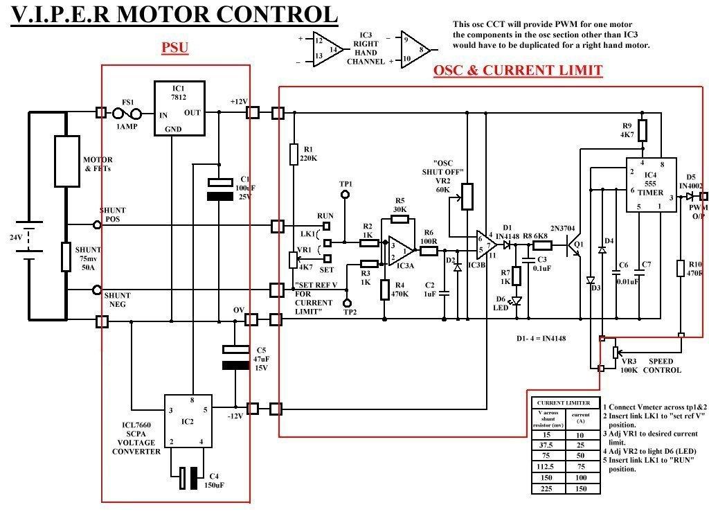
This controller is for use with 4 banks of FETs and 4 single pole relays in an H-bridge CCT layout.
The LM324N opamp IC3 is for current limiting.
|
|
|
|
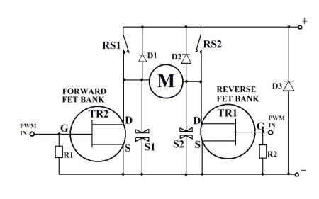
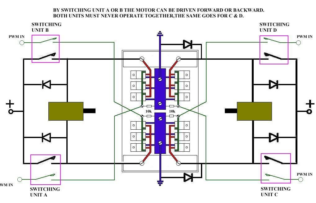
FET & relay H-bridge
This simple diagram shows the basic layout of the H-bridge CCT (so called because of the H shape of the switching layout).
RS1 & RS2 are single pole relays of the highest current rating you can obtain, you could even use car starter relays or industrial contactors.
D1, D2 & D3 are all high current diodes they are used take any EMFs (voltages generated by the motors when disconnected from the drive power) back to the battery to stop damage to the switching components.
S1 & S2 are transient suppressers they are also to reduce the chances of damage to the FETs, I will also have these across the relay contacts. If the voltage rises above a certain level (determined by the manufacturer) the suppressers become low resistance and disperse the voltage.
R1 & R2 are to pull the gate potential low when the PWM pulses are removed, if these resisters where not present the FETs could be turned ON by static or the last pulse from the PWM stream could have been a positive.
TR1 & TR2 are actually banks of FETs wired in parallel due to the low current required to switch a FET on a number can be controlled with no problem.
To drive the motor (M) one way you operate RS1 & provide PWM to TR1 and to reverse the motor you do the same for RS2 & TR2, but you must never operate both directions together unless you are thinking of having a self destruct option.
|
|
|
|
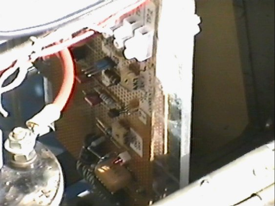
This is a picture of the PWM osc
There are 2 sides to this board one for each motor.
It is situated next to the right hand drive motor as shown below.
|
|
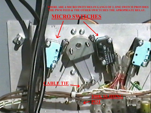
This is the servo interface.
The sliding resister controls the PWM oscillator, & the micro switches control the relays and FET groups.
|
|
|
|
|
|
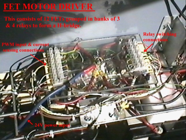
This is one option for a FET layout.
The basic idea of this speed controller is that
the PWM pulses will be off when the
direction of the motors is to be changed.
This means that there will be no current flowing
through the relays when they operate or release,
hence no burning out of the contact
faces.
Diodes are also placed across the relay contacts to
stop any back EMF from the motor when we try to
stop the motor or change direction.
The diodes will also provide regenerative breaking in
that power generated from the motor fed back to the
battery will slow the motor down and help to
increase the run time of the battery.
The 10K ohm resisters are to pull the gate
potential down to ground and hence switch off FETs
when the PWM pulses are cut off by the
micro switches on the interface board.
|
|
|
|
|